How do you make a rigid flex PCB?
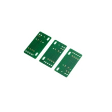
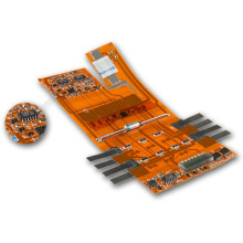
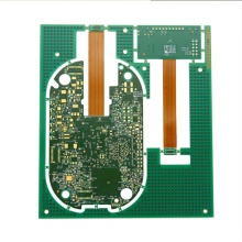
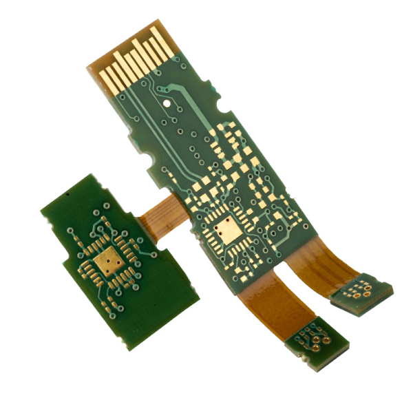
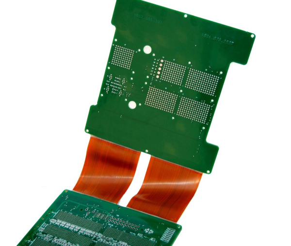
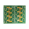
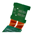
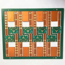
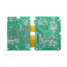
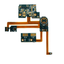
Custom pcb fabrication, rigid-flex PCB is a combination of rigid-flex PCB and flexible PCB. The two boards are permanently connected together to form various types of PCBs.
There are several steps involved in designing and manufacturing a Rigid-Flex Board. All these steps must be executed accurately to have High Quality Prototype PCB Fabrication.
The main steps involved in the manufacturing process of Rigid-Flex Board are as follows:
1. Apply adhesive/coating on the copper layer-the first and most important step in rigid-flex PCB manufacturing is to apply a suitable adhesive on the thin copper layer (in epoxy or acrylic bonding Choose between agents).
2. Add copper foil-use lamination or electroless plating to add a thin layer of copper foil on the adhesive.
3. Drilling-mechanically drill ultra-small to medium to large-sized holes into the flexible substrate. Advances in technology allow laser drilling on flexible platforms to form small to large holes. Excimer (ultraviolet) or YAG (infrared) lasers and CO2 lasers are used to achieve high accuracy.
4. Plating through holes-This is a critical step in the manufacture of Rigid-Flex Board, because it requires special care and precision. After drilling a hole on the flexible platform, copper will be deposited into it. Once completed, the copper is electrolessly plated. Usually, the manufacturer sets the through-hole plating thickness to 1 mil, and sometimes sets it to half mil.
5. Coating anti-corrosion coating-After the through hole is electroplated, a photosensitive anti-corrosion coating is applied on the flexible surface. LPI (liquid imageable image) is very suitable for this purpose. It can be applied by roll coating, spray coating or curtain coating.
6. Etching and peeling-After etching the copper film, chemically peel the resist from the circuit board.
7.Coverlay Layers-Covering layers used as solder masks are applied on the top and bottom of the flexible circuit to provide absolute protection for the PCB. One of the commonly used covering materials is a polyimide film with adhesive.
8. Cut the flexible line – This step involves cutting the flexible line, also known as blanking. Processes such as hydraulic punches and dies are used for cutting flexibility. These methods allow multiple circuit boards to be cut at the same time.
9. Laminating-After the blanking process, the flexible circuit is laminated between the rigid parts. PI and glass can be used to make thin and flexible laminates.
Electrical tests are then performed on the laminated flexible circuit to ensure its efficiency and performance.
Standardized manufacturing processes that follow the IPC (Connected Electronics Industry Association) guidelines ensure a reliable and economical rigid-flex PCB.