柔性PCB有多灵活?
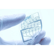
Flexible PCB is defined as an arrangement pattern of integrated circuits and components using flexible materials. Here, the same components used to produce rigid printed circuit boards can be used to manufacture these flexible electronic components, but they should allow the flexibility of the circuit board during their application.
Some of the advantages provided by flexible PCBs include: light weight, high reliability, high ductility, and space saving. However, the inventor/designer must be prepared for its complexity and complexity.
In addition to the designer being responsible for the mechanical complexity associated with the flexible circuit, there is not much difference between a flexible PCB and a rigid board in the design stage. For example, if the flexible PCB is bent beyond its performance, it will tear during installation.
Therefore, to create a mechanical model of the PCB and test it before electrical design, coordination is very important. In addition, this will include any misalignment, repair and ergonomic testing of the installation. In addition, designers need to understand the different available flexible circuits and their working principles.

Types of flexible PCB
According to its application, there are different types of existing flexible PCBs. Among them, flexibility, high-density interconnection (HDI) flexibility and rigidity are the most prominent.
The flexibility and vibration resistance of these PCBs make them unique and distinctive. They are the most common flexible versions of existing rigid PCBs. Their additional features are accompanied by the usual repeatability, high density and reliability that rigid PCBs already provide.
The ability of flexible circuits to adopt three-dimensional configurations is the main advantage of rigid PCBs. One of the most common applications for flexible PCBs is to replace wiring harnesses.
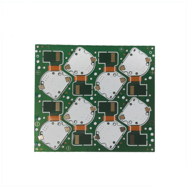
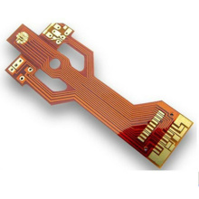
Rigid-Flex PCB
These PCBs are a combination of flexibility and rigidity. Although some unique abilities have been added that cannot be possessed by flex and rigidity when separated, they provide the best of the two structures. For example, a series of rigid PCBs derived from typical rigid-flex structures will be connected by integrated flexible circuits. Therefore, designers can greatly improve their circuit design capabilities by using rigid parts as a supplement to the flexible area.
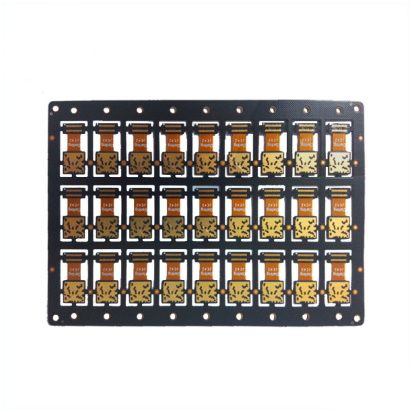
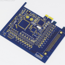
High-density interconnect (HDI PCB) flexible PCB
When the typical flexible circuit does not have enough options, HDI PCB works by combining fine functions such as micro-vias, better layout, structure, and design. In addition to the above functions, other functions include: high-density flexible circuits, enhanced functions and smaller dimensions.
HDI technology provides better electrical performance, can use advanced IC packaging, and use thinner and better reliability materials.
Advantages of Flex circuit
As for ribbon cable or discrete wiring replacement, custom repeatable wiring provided by flexible circuits is spread throughout the assembly. Because of their higher reliability, they can reduce maintenance calls.
Polyimide is a dielectric layer that covers and protects the circuit, rather than a simple sales mask. The flexible board uses this layer to cover the conductors of the flexible circuit. Manufacturers use other substrates and covering materials to handle a wider range of harsh environments and environmental conditions.
Flexible plates can withstand long bending cycles, although they can be very thin. To resist and be able to carry millions of bending cycles, these plates can be reinforced with appropriate design materials. This is to ensure that there will be no interruption in the transmission of power and signals.
When facing high acceleration and/or vibration, flexible circuits with high ductility and low quality are very good advantages. Under the same working conditions, the impact and stress of rigid PCB and its solder joints and Electronic Components are far greater than the impact of solder joints on flexible PCBs.
The advantages of flexible circuit boards make them very suitable for many applications in medical, consumer electronics, military, aerospace, industrial, automotive, transportation and communications fields.
Use of flexible circuits
The flexible circuit is shaped by the designer to fit the area and any other type of PCB cannot. Although flexible circuits have their own advantages, some people can think of them as a mixed assembly of round wires and ordinary PCBs. Someone can retain the conventional PCB density, accuracy and repeatability, and with the help of flexible circuits, can still achieve unlimited freedom of packaging geometry.
Usually, the wiring harness is replaced by a flexible circuit. In one operation, this allows a single flexible circuit to shift several cables, rigid boards and electronic connectors. Because it bundles them together and eliminates the need for color-coded wires, the assembly will proceed faster than usual. In the use of faults and the Box Build Assembly process, the possibility of rejection will decrease, and the production level will increase as the installation cost decreases.
When flexible, the repeatability of wire routing will increase the circuit to replace the wire harness. During wiring, this can eliminate errors, thereby reducing rework, test time and rejection. Since round wires cannot carry more current and dissipate heat better than flat foil conductors of the same cross-sectional area, the connection is stronger. When designers decide on a more uniform conductor pattern in a flexible circuit, they will better control noise, crosstalk, and impedance.
In addition, space and/through flexible circuits can reduce the weight of traditional wiring to approximately 75%. Compared with the use of wire harnesses, the repetitive cost of flexible circuits is lower. Compared with rigid boards, the cost of replacing and repairing flexible circuits is much lower because they are more resistant to shock and vibration. However, surface mount components can be easily mounted on flexible boards by placing adhesive reinforcement ribs in the desired area.
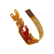
Advantages of Rigid-Flex Board
Since the rigid-flex circuit replaces the largest number of components, it is beneficial ownership when looking at the total cost of the entire device. Rigid-flex circuits provide the greatest vibration resistance and capacity, because they can mix the best resistance of the rigid area of the resistor with the elastic flexible area. In addition, surface mount Electronic Components can be mounted on both sides of the circuit board. This is the best combination option when installing a high-quality PCB assembly, because it can provide a better and smoother transition between the flexible area and the rigid area, while retaining its advantages.
Defining the appropriate stackup for a multilayer PCB is one of the most important facts in the preliminary design. For large and dense PCBs with many pin count BGAs, this is very important, especially when the stack of standard laminates is insufficient in terms of performance goals and cost. If properly designed, HDI stack can well replace a large number of layers, and can provide low cost and higher performance.
For circuit boards with high pin count Surface-Mount (SMT) &BGA Assembly, there are three types of paste. They include; sequential lamination with buried and blind vias, build-up with micro vias, and standard lamination with vias. Among the three, the accumulation of micro-vias is mainly used by HDI boards, because it has many advantages:
The micro-via pattern can be used more efficiently. In this way, more wiring channels can be opened, which can reduce the number of layers.
For high-density circuit boards, it can provide the lowest cost.
Fewer layers and higher wiring density result in smaller vias and trace sizes.
Micro vias are the only practical method for designing several large BGAs with a pitch of less than 0.88mm.
Appropriate definition of overlay
They contain materials suitable for procedures that must comply with RoHS standards.
The cost is lower, and newer materials can be provided to obtain higher costs. Performance and they may not be suitable for other lamination types.
The HDI PCB laminate defined by the significant custom pcb cost fabrication is 16 layers and the overall board thickness is only about 66±7 mils. They have laser-drilled micro-vias and require sequential build (SUB).
Cost impact
Generally speaking, although rigid PCBs are cheaper than flexible circuits, as the number of layers increases, the cost will increase. Therefore, in order to minimize costs, some factors must be considered. For example, it may be more expensive to use a four-layer circuit compared to two double-layer circuits.
Support for flexible circuits, other factors may reduce overall efficiency costs. For example, you can save layers and space by folding the flexible circuit. Depending on the specific circumstances, the time investment in project evaluation may result in substantial savings.