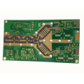
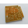
What is high frequency PCB design?
The PCB circuit board is mainly composed of pads, perforations, mounting holes, wires, Electronic components, Electronic connectors, fillers, and electrical edges. The pads are mainly metal holes for soldering component pins; and the perforations include metal perforations and non-metal perforations. The metal perforations are used to connect the component pins between the two layers; the mounting holes are used to fix the circuit board; Wires are electrical network copper films used to connect the pins of components; connectors are used to connect components between circuit boards; fillers are used to lay the ground wire network on the cable connectors to determine the circuit board Size, all components on the circuit board cannot exceed this limit.
When designing high-frequency board , the power supply is designed in the form of layers, which in most cases is greatly improved compared to the bus method, so that the circuit is designed along the path of minimum impedance. In addition, the power board must provide a signal loop for all generated and received signals on the PCB in order to minimize the signal loop, thereby reducing noise that is often ignored by low-frequency circuit designers.
The design of high-frequency PCB must be unified and stable between the power supply and the ground; wiring and proper termination can eliminate reflections; carefully considered wiring and proper termination can reduce small capacitive and inductive crosstalk; noise must be suppressed to meet EMC Require.
When manufacturing high-frequency circuit boards, the dielectric loss (Df) is small, which mainly affects the signal transmission quality. The smaller the dielectric loss, the smaller the signal loss; the lower the water absorption rate, the higher the water absorption rate, which will affect the dielectric loss and the dielectric loss will be affected. The dielectric constant (DK) must be small and stable. Generally, the lower the transmission speed of the signal, the better. The transmission speed of the signal and the dielectric constant of the material can easily lead to signal transmission delay; as much as possible to be consistent with the thermal expansion coefficient of the copper foil, because inconsistencies will cause the copper foil to separate in the cold and heat changes; other heat resistance, chemical resistance, Impact strength, peel strength, etc.