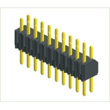
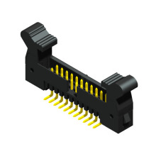
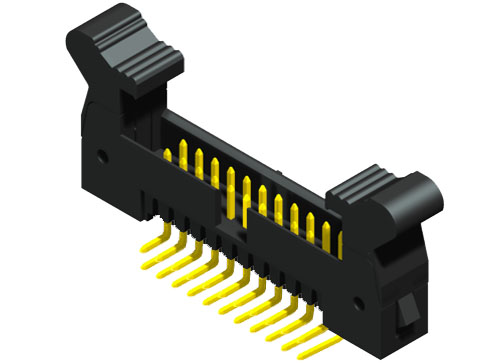
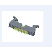
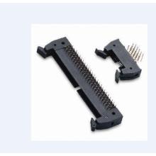
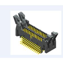
• The ejector header is a European connector, which is a variety of connectors classified according to the actual use. It is named because its shape is similar to the horn. The ejector header is a very simple internal wiring device.
• a) Climate category.
• b) Withstand voltage.
• c) Type B, C, M, Q, R of 79483MD: 20m Ω; type D, E, F, G, S, T, U, V: 15m Ω; type H: 8m Ω.
• d) Insulation resistance 10M Ω min.
• e) Maximum speed of mechanical operation: 10mm/s, interval time: 30s (no connection).
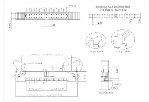
• 1 Insertion direction.
• When the ejector header is fully inserted to U=14.2, the specified 79483MD shall be guaranteed.
• 2 Perpendicular to the insertion direction.
• If the printed board or fixed board mounted connector is floating mounted, the design of free and fixed board.
• mounted connectors shall give an adjustable displacement of at least 1mm (Note: for rigid mounting of fixed board.
• mounted connectors, the mounting frame must have a strict tolerance.)
• 3 Inclination.
• The design of free and fixed board mounted connectors allows inclination error, with longitudinal axis of ± 4 °.
• and transverse axis of ± 4 °.
• European style and its mixed connectors are usually used in backplane interconnection system, and the selected
• connectors shall meet the following requirements:
• a) Type C, R and M shall be preferred, and their overall dimensions and installation methods shall comply with
• relevant provisions of IEC60603-2. PCB punching drawing shall refer to relevant drawings in connector parameter
• library.
• b) Reference System for European Style Connectors
• On the mounting surface of the fixed plate connector, the line passing through the center of the mounting hole is
• taken as the reference line. Use the nominal center near the mounting hole of No. 32 contact as the reference
• point.
• c) For RF mixed type connectors, the frequency range, impedance characteristics, VSWR and insertion loss of RF
• terminals shall meet certain requirements. The mixed type connector with power terminals shall meet certain power requirements. When installing the mixed type connector, there must be appropriate tolerance and guidance
• requirements. It is best to achieve floating installation.
• d) The selected connector shall be easy to install, and all European connectors shall have the same installation
• characteristics
• e) The connector shall have reliable contact, good conductive insulation performance, sufficient mechanical strength, and the number of times of insertion and removal shall meet the provisions of relevant international and domestic standards.
• f) Considering the requirements of PCB thickness on the length of connector pins, the exposed height of the pins of perforated and welded connectors is ≥ 1mm to ensure reliable welding.
• g) The cable and connector connecting the signal must ensure impedance matching.
• h) If there are EMC requirements, the connector must meet EMC requirements.
• i) Connector termination forms include crimping, PCB welding and other forms, which can be selected according to actual needs.