Choose Shipping Method
Shipping Method Estimated Delivery Time Shipping Cost
Home > Electronic Components, Accessories & Telecommunications > Other Electronic Components > resistance smd resistors elect...
  • 0 Piece/Pieces $ 0
  • ship to United States To Be Negotiated $ /
  • Lead time / days
    After payment is complete, your order will ship within
  • Shipping time / days
    Estimated Delivery Time is the time between your package shipped out of carriers’ warehouses and final destination delivery. Estimated delivery time does not include supplier manufacturing lead time, holidays and weekends.
Totals $ /
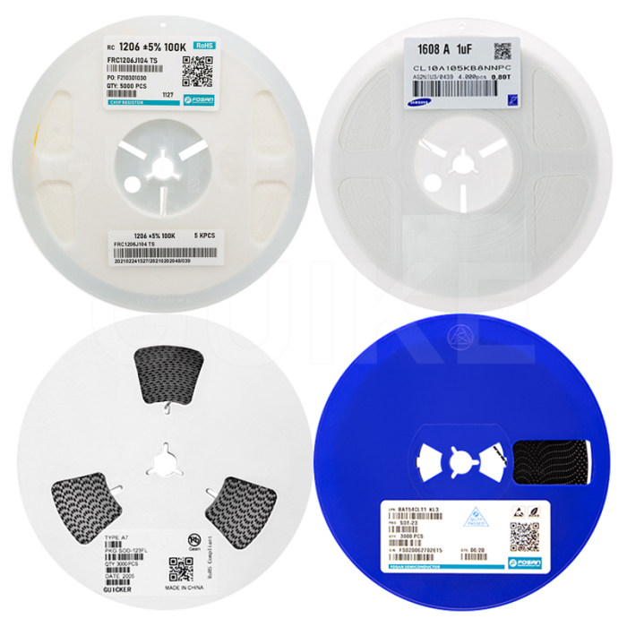
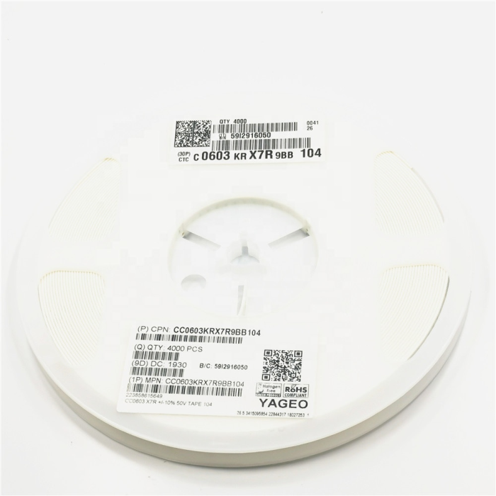
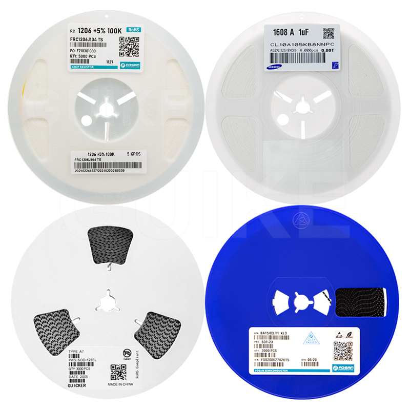
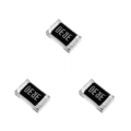
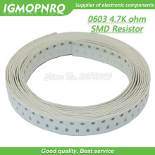
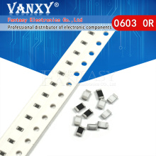
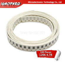
resistance smd resistors electronic components
  • resistance smd resistors electronic components
  • resistance smd resistors electronic components
  • resistance smd resistors electronic components
  • resistance smd resistors electronic components
  • In Stock
  • Ready to Ship
  • Fast Dispatch

resistance smd resistors electronic components

  • $1.6
    ≥1
    Piece/Pieces
1 Piece/Pieces (Min. Order)
Quantity:

0 Piece,Product Price: US $ 0

  • Lead Time:/ days
  • Shipping time:/ days
Sample:
$20.00 /Piece/Pieces, 5 Piece/Pieces (Max. Order)Buy Samples
  • Product Description
Overview
Product Attributes
Model No.:
resistors electronic components
place of origin:
China
Operating Temperature:
-40°c ~ 85°c (Ta)
Mounting Type:
Surface Mount
Mfr:
Macronix
Package / Case:
8-Soic (0.209", 5.30mm Width)
Memory Size:
128mb (16m X 8)
Voltage - Supply:
2.7v ~ 3.6v
Clock Frequency:
133 Mhz
Memory Interface:
Spi - Quad I/O, Qpi
Write Cycle Time - Word, Page:
40µs, 1.2ms
Packaging & Delivery
Selling Units:
Piece/Pieces
Single package size:
12cm*12cm*24cm
Single gross weight:
2kg
Package Type:
Vaccum and ESD
Picture Example:
Lead Time :
Quantity(Piece/Pieces) 1 ~ 2500>2500
Est. Time(days) 3To be negotiated

If you finish the payment today, your order will ship out within the delivery date.

How do you measure resistance of electronic components?

The basic idea is that the multimeter places a voltage at the two probes and this will cause a current to flow in the item for which the Electronic Resistor and Capacitor is being measured. By measuring the resistance it is possible to determine the resistance between the two probes of the multimeter, or other item of test equipment.

1. Cut off the Heavy copper board circuit power.
If the circuit contains a capacitor, discharge the capacitor before taking any resistance readings.
2. Turn the dial of the digital megohmmeter to resistance or ohms, which usually shares a point on the dial with one or more other test/measurement modes (continuity, capacitance or diode; see figure below).
The display should show OLΩ, because in resistance mode, the digital megohmmeter will automatically start resistance measurement even before connecting the test leads to the component sourcing.
The M of symbol may appear in the display because the resistance of the disconnected (unconnected) test lead is very high.
When the wire is connected to the component, the digital megohmmeter will automatically adjust it to the best range using the "auto range" mode.
By pressing the range button, the technician can manually set the range.
If the component to be tested is removed from the circuit, the best result will be obtained. If the component is left in the circuit, the reading may be affected by other components in parallel with the component to be tested in Wave Solder for PCBA .
3. First, insert the black test wire into the COM jack.
4. Then insert the red wire into the VΩ jack.
When finished, remove the wires in the reverse order: first red, then black.
5. Pass the test leads across the component under test.
Make sure that the contact between the test leads and the PCB circuit is good.
Tip: For very low resistance measurements, please use the relative mode (REL; see point 11). It can also be referred to as zero or incremental (Δ) mode. It automatically subtracts the test lead resistance-usually 0.2 to 0.5. Ideally, if the test leads are in contact (shorted together), the display should show 0Ω.
Other factors that may affect the resistance reading: foreign matter (dirt, flux, oil), the PCBA circuit path of the body in contact with the metal end of the test lead or in parallel. The human body becomes a parallel resistance path, reducing the total circuit resistance. Therefore, avoid touching the metal parts of the test leads to avoid errors.
6. Read the measured value on the display.
7. When finished, turn off the megohmmeter to prevent the battery from draining.
Advanced digital megohmmeter options
8. Press the RANGE button to select a specific fixed measurement range.
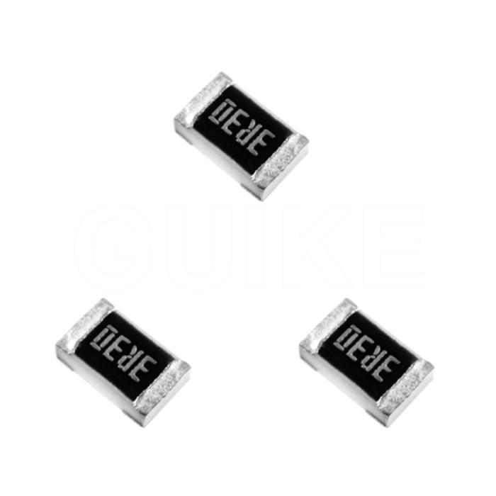
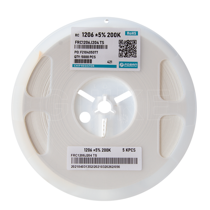
Resistance Smd Resistors Electronic Components 4 PngResistance Smd Resistors Electronic Components 3 PngResistance Smd Resistors Electronic Components 2 PngResistance Smd Resistors Electronic Components 1 Png


Wholesale Resistance Smd Resistors Electronic Components
Are you still worrying about not finding the resistance smd resistors electronic components? Come and find the resistance smd resistors electronic components you want on Bossgoomall. If you want to know more about the products in resistance smd resistors electronic components, Please click on the product details to view. we have the perfect after-sales service and technical support. Looking forward to your use of our products.
Home > Electronic Components, Accessories & Telecommunications > Other Electronic Components > resistance smd resistors elect...
Add To Cart Start Order
Sign in
Account
Password