Choose Shipping Method
Shipping Method Estimated Delivery Time Shipping Cost
Home > Electronic Components, Accessories & Telecommunications > PCB & PCBA > Double-Sided PCB > Air Flow Meter PCB Assembly
  • 0 Piece/Pieces $ 0
  • ship to United States To Be Negotiated $ /
  • Lead time / days
    After payment is complete, your order will ship within
  • Shipping time / days
    Estimated Delivery Time is the time between your package shipped out of carriers’ warehouses and final destination delivery. Estimated delivery time does not include supplier manufacturing lead time, holidays and weekends.
Totals $ /
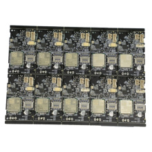
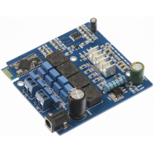
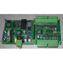
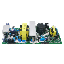
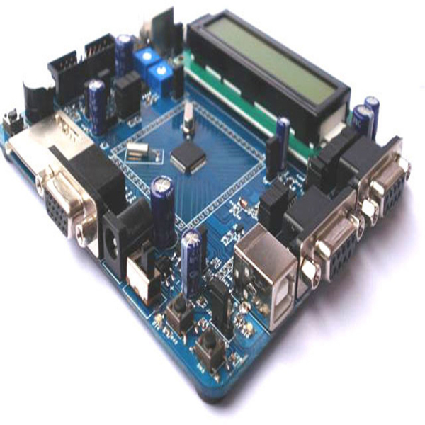
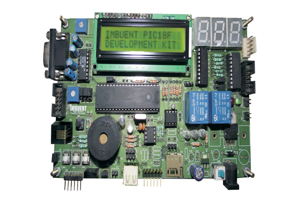
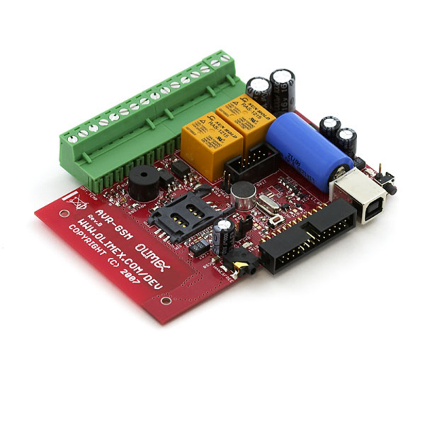
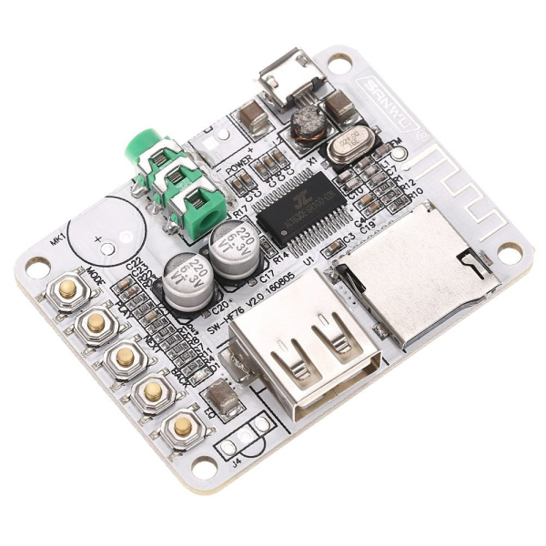
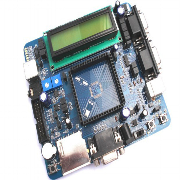
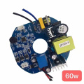
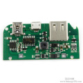
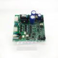
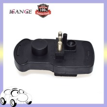
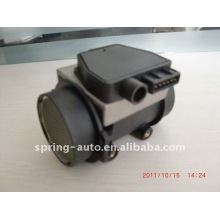
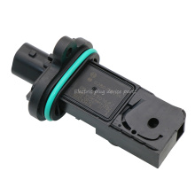
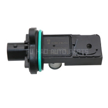
Air Flow Meter PCB Assembly
  • Air Flow Meter PCB Assembly
  • Air Flow Meter PCB Assembly
  • Air Flow Meter PCB Assembly
  • Air Flow Meter PCB Assembly
  • Air Flow Meter PCB Assembly
  • Air Flow Meter PCB Assembly
  • Air Flow Meter PCB Assembly
  • Air Flow Meter PCB Assembly
  • In Stock
  • Ready to Ship
  • Fast Dispatch

Air Flow Meter PCB Assembly

  • $19.9
    ≥1
    Piece/Pieces
1 Piece/Pieces (Min. Order)
Quantity:

0 Piece,Product Price: US $ 0

  • Lead Time:/ days
  • Shipping time:/ days
  • Product Description
Overview
Product Attributes
Model No.:
Air Flow Meter PCB
Base Material:
Fr4,
Min. Line Width:
0.075mm
Board Thickness:
0.1-4mm±10%, 0.1-4mm±10%
Min. Line Spacing:
0.075mm
Copper Thickness:
0.5-4 0z
Min. Hole Size:
0.2mm
Packaging & Delivery
Selling Units:
Piece/Pieces
Single package size:
12cm*8cm*0.02cm
Single gross weight:
0.036kg
Package Type:
Vacuum packing
Lead Time :
Quantity(Piece/Pieces) 1 ~ 1000>1000
Est. Time(days) 9To be negotiated

If you finish the payment today, your order will ship out within the delivery date.

How is PCB designed?

PCB layout design:
1.1 Preparations before layout:
1) Check whether the capture point setting is correct. 08 process is 0.1, 06 process is 0.05, 05 process is 0.025.2. Cell name cannot start with a number. Otherwise, DRACULA check cannot be done.
2) Consider the direction and location of the PIN before layout
3) Analyze the circuit before layout, and draw the MOS tubes of the same function together
4) Pre-order the direction of the two layers of metal. The direction of the grid in a picture should be as consistent as possible, not horizontal and vertical.
1.2 Layout principles
1.3 Component arrangement rules
1). Under normal conditions, all Electronic Components should be arranged on the same side of the printed circuit. Only when the top Electronic Components are too dense can some devices with limited height and low heat generation, such as chip resistors, Chip capacitors and ICs are placed on the bottom layer.
2). On the premise of ensuring electrical performance, Electronic Components should be placed on the grid and arranged in parallel or perpendicular to each other in order to be neat and beautiful. Generally, no overlapping of components is allowed; the arrangement of components should be compact, and input and output components should be as close as possible. keep away.
3). Certain components or Cable Connectors I/O Connectors may have a higher potential difference, and the distance between them should be increased to avoid accidental short circuits caused by discharge and breakdown.
4). Components with high voltage should be arranged as far as possible in places that are not easily reachable by hands during debugging.
5). Components located at the edge of the board should be at least 2 board thickness away from the edge of the board
6). The components should be distributed evenly and densely on the entire board to facilitate Surface-Mount (SMT) &BGA Assembly.
2.High frequency board according to the signal direction layout principle
3. Prevent electromagnetic interference
4. Suppress heat and dry winding. Try to use metal base printed board.
5. The layout of adjustable components is convenient for PCBA Manufacturing.
For the layout of adjustable components such as potentiometers, variable capacitors, adjustable inductors or micro switches, the structural requirements of the whole machine should be considered. If it is adjusted outside the machine, its position should be the same as the position of the adjustment knob on the chassis panel.
Adaptable; if it is adjusted inside the machine, it should be placed on the printed circuit board where it is adjusted.
.

Professional Oem Electronic Kit Air Flow Meter Pcb Assembly Manufacturer Electronic Manufacturing Design Reliable Smt Factory JpgIndustrial Control Pcb Pcba JpgAir Flow Sensors Pcb JpgAir Flow Meter Pcb JpgAir Flow Meter Pcb Assembly Jpg


Wholesale Air Flow Meter Pcb Assembly
You can browse a wide variety of products in every type to suit different parts of air flow meter pcb assembly. Browse traditional air flow meter pcb assembly, air flow sensors pcb and air flow meter pcb in different shapes, styles and sizes to suit the requirements and shop them at budget-friendly prices here. Our Bossgoomall offer great deals on these products to let you save a lot of money when you shop for decorative air flow meter pcb assembly, industrial control pcb pcba, air flow sensors pcb, air flow meter pcb, industrial control pcb pcba products at Bossgoomall. All these products are branded and known for effectiveness, vitality and long life. Change the mood of your place by picking from cost-effective and beautiful air flow meter pcb assembly products available at Bossgoomall!
Home > Electronic Components, Accessories & Telecommunications > PCB & PCBA > Double-Sided PCB > Air Flow Meter PCB Assembly
Add To Cart Start Order
Sign in
Account
Password