-
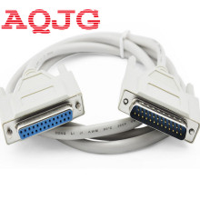
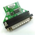
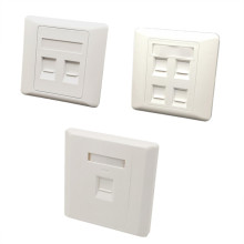
USB2.0 standard, usb2rs232 adapter cable with db25 male, full pinout
-
Support USB B female to RS232 DB25
-
win10 sinforcon silicon cp2102 or ftdi ft232rl usb rs232 adapter cable with standard db9 virtual com port full pinout
-
ftdi usb rs232 adapter cable with db9 male full pinout
-
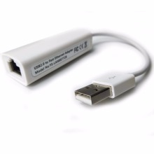
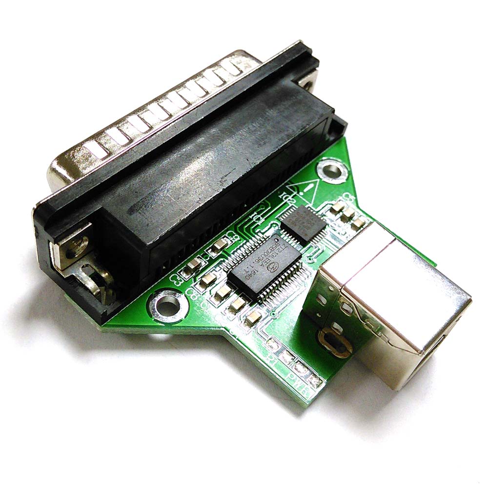
USB to RS232 adapter
-
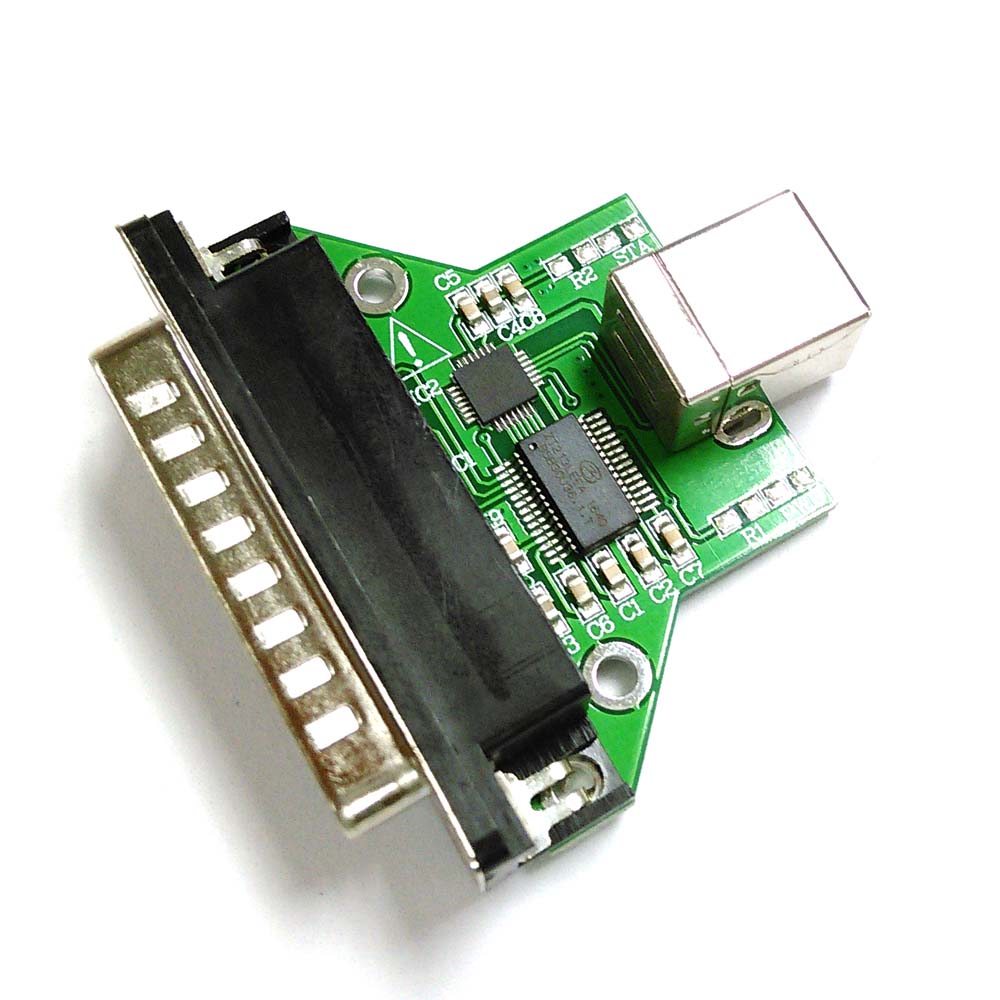
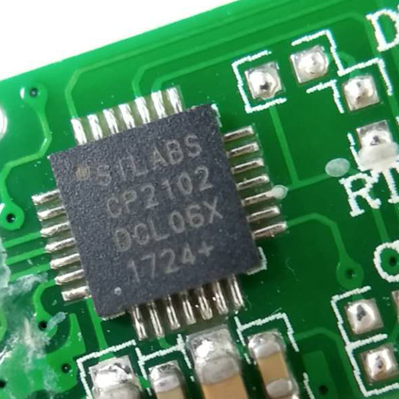
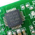
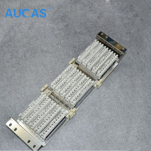
CP2102 for usb to uart and ZT213 for uart to rs232
-
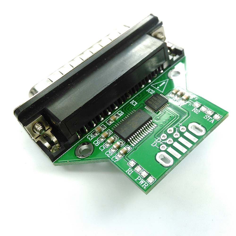
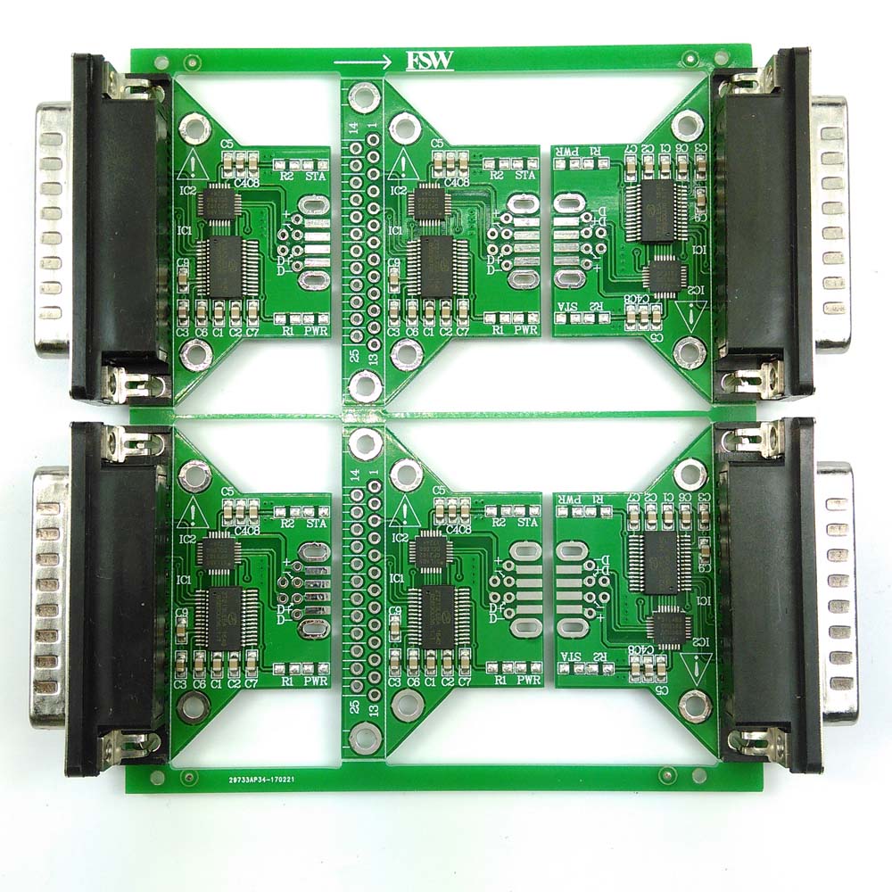
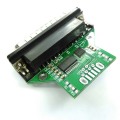
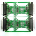
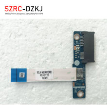
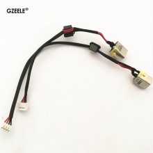
USB RS232 adapter PCBA
-
1-DCD, 2-RX, 3-TX, 4-DTR, 5-GND,6-DSR, 7-RTS, 8-CTS, 9-RI for DB25 male adapter
-
Support USB B female connector on usb side
-
Support Win XP, Win 7, Win 8, Win 8.1, win 10, Mac, Android, Linux, Win CE, etc
-
Board thickness: 1.6mm
-
Intergrated 1024 byte EEPROM for PID,VID re-write
-
With Leds on board for power and data transfering
-
Nuts on DB9 side
-
CE, RoHS, FCC compliance
-
PE bag for each, then in carton
Installing the usb serial driver automatically
About CP2102
Single-Chip USB to UART Data Transfer
-Integrated USB transceiver; no external resistors required
-Integrated clock; no external crystal required
-Internal 1024-byte programmable ROM for vendor ID, product ID, serial number, power descriptor, release number, and product description strings
- EEPROM (CP2102)
- EPROM (One-time programmable) (CP2109)
-On-chip power-on reset circuit
-On-chip voltage regulator
- 3.3 V output (CP2102)
- 3.45 V output (CP2109)
-100% pin and software compatible with CP2101
USB Function Controller
-USB Specification 2.0 compliant; full-speed (12 Mbps)
-USB suspend states supported via SUSPEND pins
Asynchronous Serial Data BUS (UART)
-All handshaking and modem interface signals
-Data formats supported:
- Data bits: 5, 6, 7, and 8
- Stop bits: 1, 1.5, and 2
- Parity: odd, even, mark, space, no parity
-Baud rates: 300 bps to 1 Mbps
-576 Byte receive buffer; 640 byte transmit buffer
-Hardware or X-On/X-Off handshaking supported
-Event character support
-Line break transmission
Virtual COM Port Device Drivers
-Works with existing COM port PC Applications
-Royalty-free distribution license
-Windows 10/8/7/Vista/Server 2003/XP/2000
-Mac OS-X/OS-9
-Linux
USBXpress™ Direct Driver Support
-Royalty-Free Distribution License
-Windows 7/Vista/XP/Server 2003/2000
-Windows CE
Example Applications
-Upgrade of RS-232 legacy devices to USB
-Cellular phone USB interface cable
-USB interface cable
-USB to RS-232 serial adapter
Supply Voltage
-Self-powered: 3.0 to 3.6 V
-USB bus powered: 4.0 to 5.25 V
CP2102 USB to UART Bridge VCP Drivers
The CP210x USB to UART Bridge Virtual COM Port (VCP) drivers are required for device operation as a Virtual COM Port to facilitate host communication with products. These devices can also interface to a host using the . These drivers are static examples detailed in application note 197: The Serial Communications Guide for the CP210x, download an example below:
Download Software
The CP210x Manufacturing DLL and Runtime DLL have been updated and must be used with v6.0 and later of the CP210x Windows VCP Driver. Application Note Software downloads affected are AN144SW.zip, AN205SW.zip and AN223SW.zip. If you are using a 5.x driver and need support you can download archived .
Download for Windows 7/8/8.1/10 (v6.7.3)
|
Platform
|
Software
|
Release Notes
|
|
Windows 7/8/8.1/10
|
(Default)
|
|
|
Windows 7/8/8.1/10
|
|
|
Download for Windows XP/Server 2003/Vista/7/8/8.1 (v6.7)
|
Platform
|
Software
|
Release Notes
|
|
Windows XP/Server 2003/Vista/7/8/8.1
|
|
|
Download for Windows 2K (v6.3a)
|
Platform
|
Software
|
Release Notes
|
|
Windows 2K
|
|
|
Download for WinCE
|
Platform
|
Software
|
Release Notes
|
|
WinCE 6.0 (2.1)
|
|
|
|
WinCE 5.0 (2.1)
|
|
|
Download for Macintosh OSX (v4)
|
Platform
|
Software
|
Release Notes
|
|
Mac OSX
|
|
|
Download for Linux
|
Platform
|
Software
|
Release Notes
|
|
Linux 3.x.x
|
|
|
|
Linux 2.6.x
|
|
|
*Note: The Linux 3.x.x version of the driver is maintained in the current Linux 3.x.x tree at .
Download for Android
|
Platform
|
Application Note
|
|
Android 4.2
|
|
What is RS232
Communication as defined in the RS232 standard is an asynchronous serial communication method. The word serial means, that the information is sent one bit at a time. Asynchronous tells us that the information is not sent in predefined time slots. Data transfer can start at any given time and it is the task of the receiver to detect when a message starts and ends. Asynchronous communication has some advantages and disadvantages which are both discussed in the next paragraph.
RS232 bit streams
The RS232 standard describes a communication method where information is sent bit by bit on a physical channel. The information must be broken up in data words. The length of a data word is variable. On PC's a length between 5 and 8 bits can be selected. This length is the netto information length of each word. For proper transfer additional bits are added for synchronisation and error checking purposes. It is important, that the transmitter and receiver use the same number of bits. Otherwise, the data word may be misinterpreted, or not recognized at all.
With synchronous communication, a clock or trigger signal must be present which indicates the beginning of each transfer. The absence of a clock signal makes an asynchronous communication channel cheaper to operate. Less lines are necessary in the cable. A disadvantage is, that the receiver can start at the wrong moment receiving the information. Resynchronization is then needed which costs time. All data received in the resynchronization period is lost. Another disadvantage is that extra bits are needed in the data stream to indicate the start and end of useful information. These extra bits take up bandwidth.
Data bits are sent with a predefined frequency, the baud rate. Both the transmitter and receiver must be programmed to use the same bit frequency. After the first bit is received, the receiver calculates at which moments the other data bits will be received. It will check the line voltage levels at those moments.
With RS232, the line voltage level can have two states. The on state is also known as mark, the off state as space. No other line states are possible. When the line is idle, it is kept in the mark state.
Start bit
RS232 defines an asynchronous type of communication. This means, that sending of a data word can start on each moment. If starting at each moment is possible, this can pose some problems for the receiver to know which is the first bit to receive. To overcome this problem, each data word is started with an attention bit. This attention bit, also known as the start bit, is always identified by the space line level. Because the line is in mark state when idle, the start bit is easily recognized by the receiver.
Data bits
Directly following the start bit, the data bits are sent. A bit value 1 causes the line to go in mark state, the bit value 0 is represented by a space. The least significant bit is always the first bit sent.
Parity bit
For error detecting purposes, it is possible to add an extra bit to the data word automatically. The transmitter calculates the value of the bit depending on the information sent. The receiver performs the same calculation and checks if the actual parity bit value corresponds to the calculated value. This is further discussed in another paragraph.
Stop bits
Suppose that the receiver has missed the start bit because of noise on the transmission line. It started on the first following data bit with a space value. This causes garbled date to reach the receiver. A mechanism must be present to resynchronize the communication. To do this, framing is introduced. Framing means, that all the data bits and parity bit are contained in a frame of start and stop bits. The period of time lying between the start and stop bits is a constant defined by the baud rate and number of data and parity bits. The start bit has always space value, the stop bit always mark value. If the receiver detects a value other than mark when the stop bit should be present on the line, it knows that there is a synchronization failure. This causes a framing error condition in the receiving UART. The device then tries to resynchronize on new incomming bits.
For resynchronizing, the receiver scans the incomming data for valid start and stop bit pairs. This works, as long as there is enough variation in the bit patterns of the data words. If data value zero is sent repeatedly, resynchronization is not possible for example.
The stop bit identifying the end of a data frame can have different lengths. Actually, it is not a real bit but a minimum period of time the line must be idle (mark state) at the end of each word. On PC's this period can have three lengths: the time equal to 1, 1.5 or 2 bits. 1.5 bits is only used with data words of 5 bits length and 2 only for longer words. A stop bit length of 1 bit is possible for all data word sizes.
RS232 physical properties
The RS232 standard describes a communication method capable of communicating in different environments. This has had its impact on the maximum allowable voltages etc. on the pins. In the original definition, the technical possibilities of that time were taken into account. The maximum baud rate defined for example is 20 kbps. With current devices like the 16550A UART, maximum speeds of 1.5 Mbps are allowed.
Voltages
The signal level of the RS232 pins can have two states. A high bit, or mark state is identified by a negative voltage and a low bit or space state uses a positive value. This might be a bit confusing, because in normal circumstances, high logical values are defined by high voltages also. The voltage limits are shown below.
RS232 voltage values Level Transmitter
capable (V) Receiver
capable (V)
Space state (0) +5 ... +15 +3 ... +25
Mark state (1) -5 ... -15 -3 ... -25
Undefined - -3 ... +3
More information about the voltage levels of RS232 and other serial interfaces can be found in the interface comparison table.
The maximum voltage swing the computer can generate on its port can have influence on the maximum cable length and communication speed that is allowed. Also, if the voltage difference is small, data distortion will occur sooner. For example, my laptop mark's voltage is -9.3 V, compared to -11.5 V on my desktop computer. The laptop has difficulties to communicate with Mitsubishi PLC's in industrial environments with high noise levels where the desktop computer has no data errors at all using the same cable. Thus, even far beyond the minimum voltage levels, 2 volts extra can make a huge difference in communication quality.
Despite the high voltages present, it is not possible to destroy the serial port by short circuiting. Only applying external voltages with high currents may eventually burn out the driver chips. Still then, the UART won't be damaged in most cases.
Maximum cable lengths
Cable length is one of the most discussed items in RS232 world. The standard has a clear answer, the maximum cable length is 50 feet, or the cable length equal to a capacitance of 2500 pF. The latter rule is often forgotten. This means that using a cable with low capacitance allows you to span longer distances without going beyond the limitations of the standard. If for example UTP CAT-5 cable is used with a typical capacitance of 17 pF/ft, the maximum allowed cable length is 147 feet.
The cable length mentioned in the standard allows maximum communication speed to occur. If speed is reduced by a factor 2 or 4, the maximum length increases dramatically. Texas Instruments has done some practical experiments years ago at different baud rates to test the maximum allowed cable lengths. Keep in mind, that the RS232 standard was originally developed for 20 kbps. By halving the maximum communication speed, the allowed cable length increases a factor ten!
RS232 cable length according to Texas Instruments Baud rate Maximum cable length (ft)
19200 50
9600 500
4800 1000
2400 3000
Error detection
One way of detecting errors is already discussed. It is the frame detection mechanism which is used to test if the incomming bits were properly surrounded by a start and stop bit pair. For further error checking, a parity bit can be used. The use of this bit is however not mandatory. If the existence of wrong bits is rare (when communicating with an internal modem for example) or if a higher level protocol is used for error detection and correction (Z-modem, RAS, etc) communication speed can be increased by not using the parity feature present on the UART.
Parity is a simple way to encode a data word to have a mechanism to detect an error in the information. The method used with serial communications adds one bit to each data word. The value of this bit depends on the value of the data word. It is necessary that both the transmitter and receiver use the same algorithm to calculate the value of the parity bit. Otherwise, the receiver may detect errors which are not present.
Even parity
Basically, the parity bit can be calculated in two ways. When even parity is used, the number of information bits sent will always contain an even number of logical 1's. If the number of high data bits is odd, a high value parity bit is added, otherwise a low bit will be used.
Odd parity
The odd parity system is quite similar to the even parity system, but in this situation, the number of high bits will always be odd.
Disadvantages of the parity system
The parity system using one bit for each data word is not capable of finding all errors. Only errors which cause an odd number of bits to flip will be detected. The second problem is, that there is no way to know which bit is false. If necessary, a higher level protocol is necessary to inform the sender that this information must be resent. Therefore, on noisy lines, often other detection systems are used to assure that the sent information is received correctly. These systems mostly do not operate on single data words, but on groups of words.