

0 Piece,Product Price: US $ 0
| Quantity(Piece/Pieces) | 1 ~ 1000 | >1000 |
| Est. Time(days) | 7 | To be negotiated |
If you finish the payment today, your order will ship out within the delivery date.
Warm Prompt
This is DIY product. We will provide source code, related documents, but do not provide technical support. Please know.
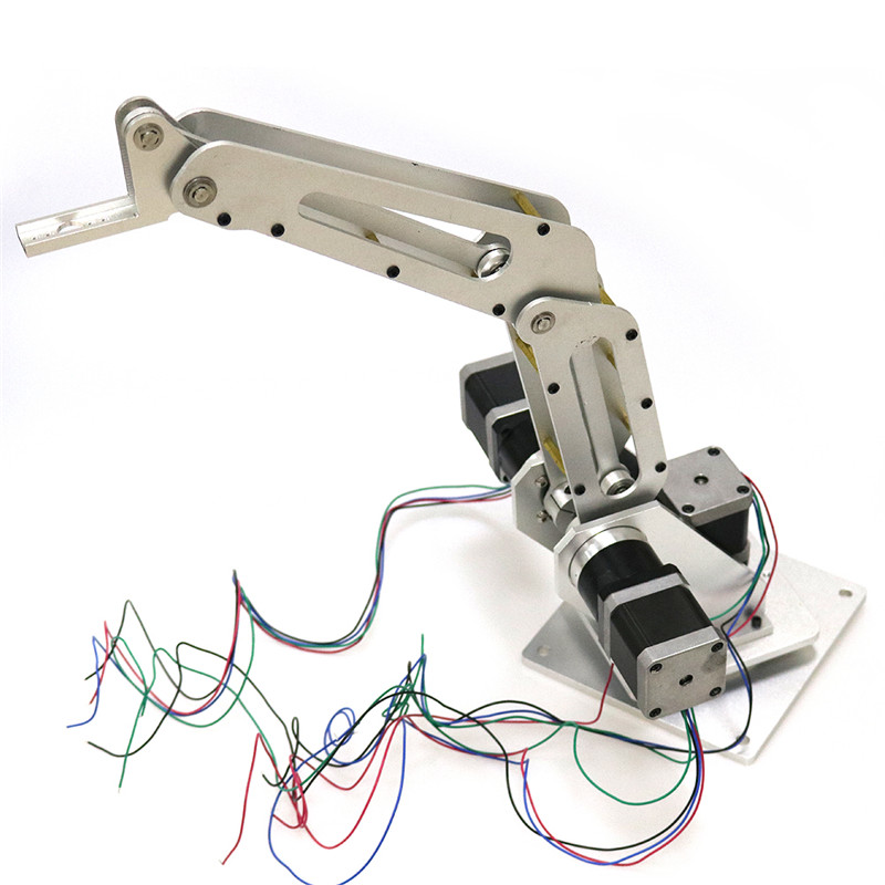
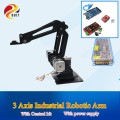
Product Introduction
Product Features
Product Parameters
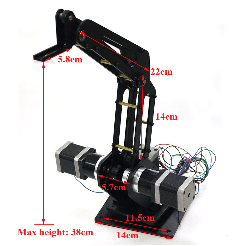
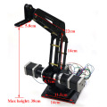
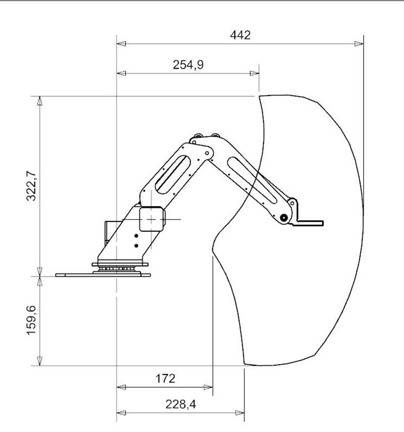
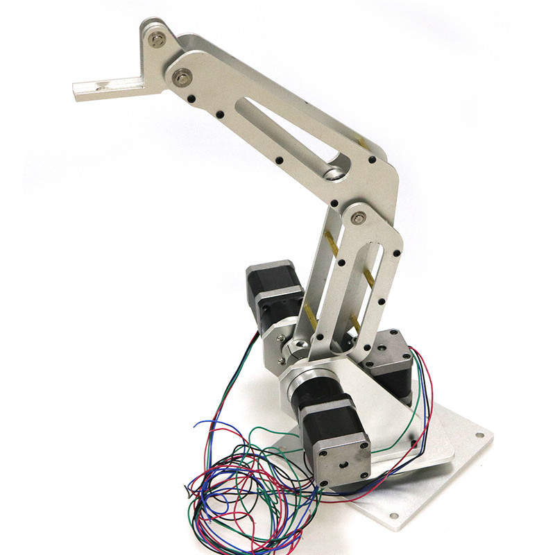
Robot Arm Parameters

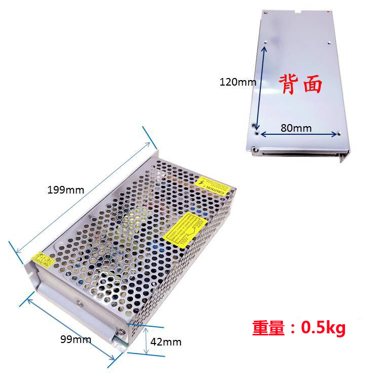
Input voltage range: 110V / 220VAC ± 20% 47-63Hz
Input current: 1A / 110V 0.4A / 220V
Output voltage / current: 12V DC / 0-10A
Work efficiency: ≥80%
Load stability: ± 2%
Inrush current: cold start current 20A / 110V 40A / 220V
Leakage current <1mA / 240VAC
DC voltage adjustable range: output voltage 10%
Ripple and noise: 100mv
Overload protection: 105-150% hiccup mode, automatic recovery
Overvoltage protection: 115-135% cut off output, automatic recovery
Short circuit protection: power failure, automatic recovery
Start / rise / hold time: 200ms, 50ms, 20ms
Operating temperature / humidity: -10 ° C ~ 60 ° C, 20% ~ 90RH
Weight / Packaging / Size: 0.5kg, 50pcs / box, 199 * 99 * 42mm.

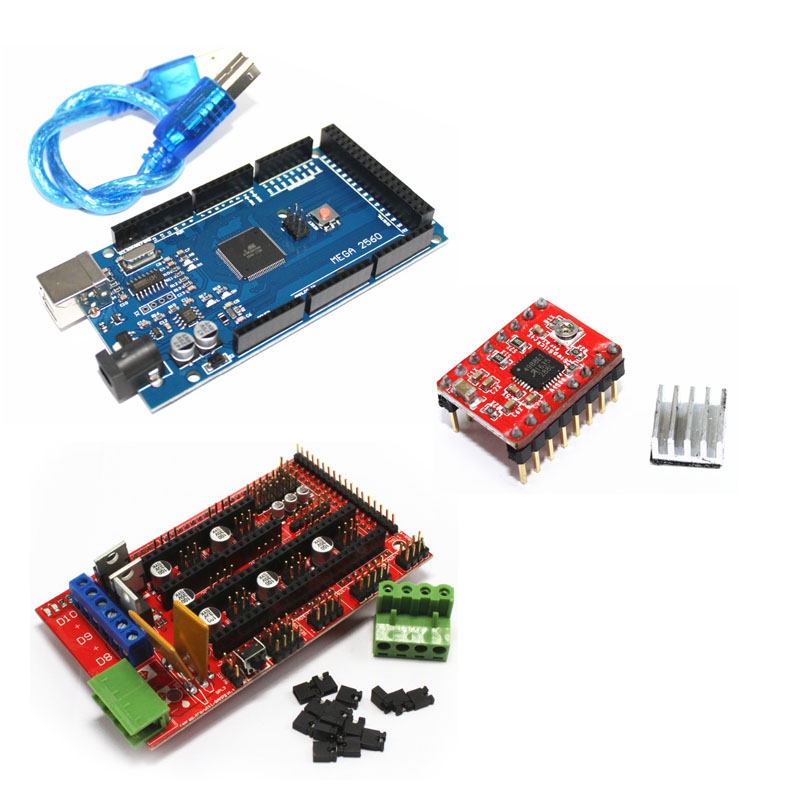
Parameters of Control Kit

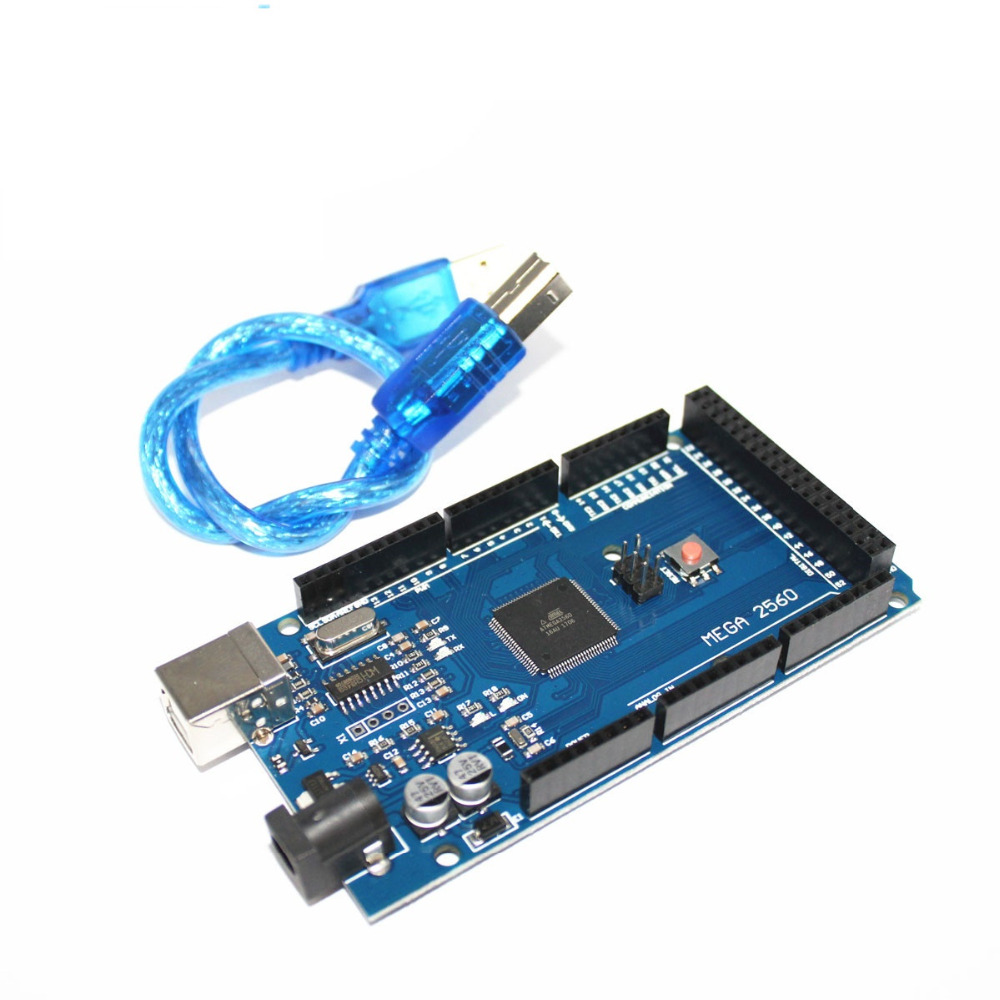
1. Mega 2560 Development Board R3
(Compatible with CH340G improved USB power supply)
Power design
There are two options for Mega's power supply system, USB direct or external power supply .
The selection will switch automatically. External power supply can choose AC-to-DC adapter or battery,
The limit voltage range of this control board is 6V ~ 12V, but if the voltage provided is less than 6V,the 1/0 port may not be able to provide a voltage of 5V, so there will be instability;
If the voltage is greater than 12V, the voltage regulator may be overheated and more likely to damage Arduino MEGA.
Therefore, the recommended operating power supply is 6.5 ~ 12V, and the recommended power supply is 7V or 12V.
Summary
Microcontroller:ATmega2560
Operating Voltage:5V
Input Voltage (recommended) 7-12V
Input Voltage (imits):6-20V
Digital I/O Pins:54 (of which 15 provide PWM output)
Analog Input Pins :16
DC Current per I/O Pin :40 mA
DC Current for 3.3V Pin:50 mA
Flash Memory:256 KB of which 8 KB used by bootloader
SRAM:8KB.
EEPROM:4 KB
Clock Speed:16MHz
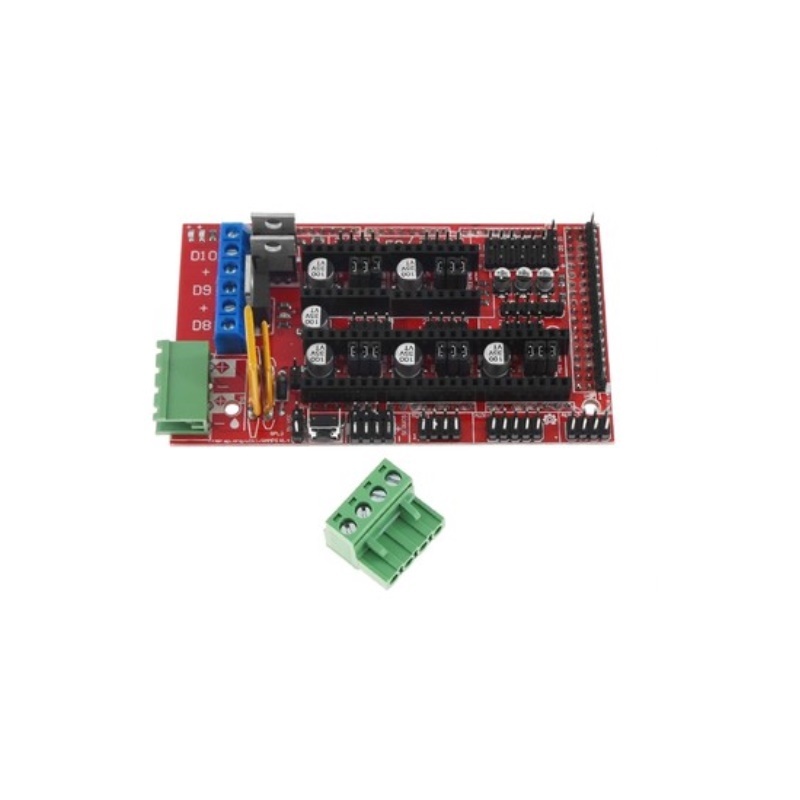
2. 3D Printer RAMPS 1.4 Control Board:
The board is mainly based on Adrian's Pololu_Electronics and Tonok. The design of the circuit is mainly based on the initial pin definition and many design improvements provided by Adrian'sPololu_Electronics Joaz RepRapSource.com

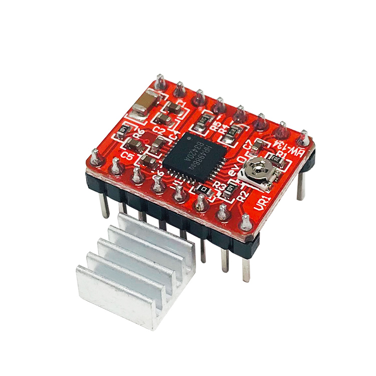
A4988 Drive Module
Parameter:
Size: 15mmX20mm (for RAMPS, ultimaker or other compatible boards);
Driven current: 2A (preferably with heat sink)
Subdivision: 1, 1/2, 1/4, 1/8, 1/16
Manufacturing process: SMT placement machine manufacturing, no manual welding, higher yield, more stable performance
Suitable for:
Where stepping motors need to be driven
It is a necessary module for building 3d printer, cnc, engraving machine and so on.
Supported 3d printers are Prusa Mendel, ultimaker, printbot, makerbot, etc.
You can refer to the Arduino code below to directly drive the motor
3D printer;
writing;
laser engraving;
seizing in factory;
repeat operations in factory;
teaching;
recognizing;
......
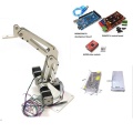
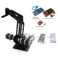
Shpping List
Silver/black with control:
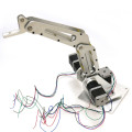
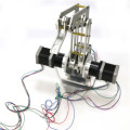
Product Images
3D Printer RAMPS 1.4 Control Board:
MEGA2560 R3:
Stepper Driver:
Product Images


Worry-free return
Product quality protection
Payment protection
Shipping protection
Copyright © 2024 BOSSGOOMALL. All rights reserved
版权所有 宁波全贸信息技术有限公司 浙ICP备12012821号-84