


| Quantity(Piece/Pieces) | 1 ~ 1000 | >1000 |
| Est. Time(days) | 7 | To be negotiated |
If you finish the payment today, your order will ship out within the delivery date.
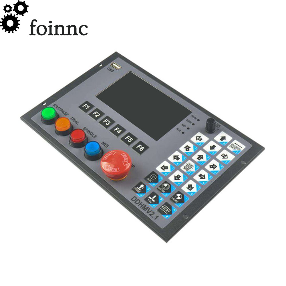
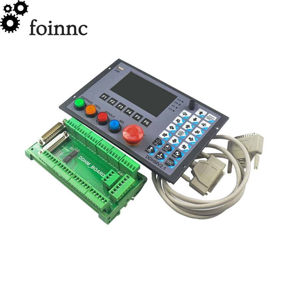
product content:
Motion controller*1 Patch panel*1 Signal line*2 U disk *1
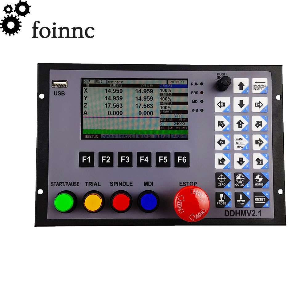
Product performance parameters:
No computer independent control is required; 13-channel optocoupler isolates the common digital input interface; 12-channel optocoupler isolates the common digital output interface; 1 way 0-10V spindle speed control analog output interface (can be modified to PWM output); Supports up to 4 channels of stepper motor control, single axis control pulse 500KHz; Stepper motor control output is differential output; The main control equipment is 24V-36V DC power input, the power capacity requirement is not less than 20W; IO power supply is 24-36V DC power input, power requirement is not less than 20W Metal case, strong anti-interference ability, excellent EMC design; Support file online editing; Support trial cutting operation; Support for tool change operation;
Productappearance structure and size:
DDHMV2.1 adopts an open structure with 4 mounting holes at the bottom, which can be used to make 4 diameters of 4mm on the cabinet. Round the hole and install the unit on the cabinet. The product dimensions are shown in Figure 1-1 and Figure 1-2. The product appearance size is 222mm*145mm*20mm; Mounting seat width 10mm The mounting hole size is 85mm*212mm. The size of the cabinet opening is (131+1)mm*(202+1)mm


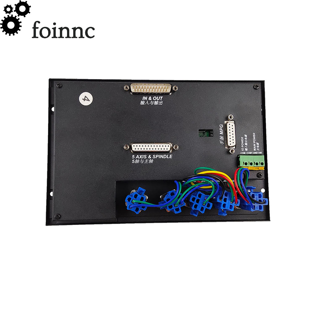
Productwiringdefinitionsandmethods:
1 power connector including main power and IO power 2 MPG interface supports standard MPG, DB15 definition reference below 3 host motor control interface This interface is connected to the interface board label 5 through the extension cable. 4 Host input and output interface This interface is connected to the interface board label 6 through the extension cable. 5 Interface board motor control interface This interface is connected to the host label 3 through an extension cable. 6 Interface board input and output interface This interface is connected to the host label 4 through an extension cable. 7 X-axis control signal output X-axis pulse and direction differential signal output, up to 1MHz frequency 8 Y-axis control signal output Y-axis pulse and direction differential signal output, up to 1MHz frequency 9 Z-axis control signal output Z-axis pulse and direction differential signal output, up to 1MHz frequency 10 A-axis control signal output A-axis pulse and direction differential signal output, up to 1MHz frequency This interface is invalid in 3-axis mode 11 B-axis control signal output B-axis pulse and direction differential signal output, up to 1MHz frequency, This interface is invalid in 3, 4 axis mode 12 Interface power supply expansion output Power supply for external expansion relay, voltage with IO power supply, COM+ For the power output +, COM- is the power output 13 Spindle control output The spindle start and stop and speed can be controlled. 14 universal input interface can be configured as limit emergency stop tool setting, etc. 15 General-purpose output interface Configurable as a digital output controlled by the M command


Input power interface:
A 4P green terminal on the back cover of the main unit is the power interface, which is labeled VIN and GND. Main power supply terminal, labeled COM+ COM- is the power supply terminal for IO module, a total of 2 sets of power supply are required, each group Both use 24V2A switching power supply.

MPG interface:

Motor control interface:


Spindle control output interface:


Input and output connection:


Worry-free return
Product quality protection
Payment protection
Shipping protection
Copyright © 2024 BOSSGOOMALL. All rights reserved
版权所有 宁波全贸信息技术有限公司 浙ICP备12012821号-84