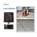
Install Detector
The detector must be installed in a convenient weatherproof location as close to the loop as possible. Installation location must choose to stay away from the heat source, it around other devices must maintain a distance of at least 10mm (mustn’t fix cling to the cabinet). A correct loop configuration and detector installation will ensure a successful inductive loop detection system. Loop of several important parameters include: loop figure, size, and turns, install methods (details as “Loop installation guide”).
Technical Data
Supply voltage 230V AC , 115V AC, 24V DC/AC, 12V DC/AC
( See the label on the detector)
Voltage tolerance AC: +10% / -15%
Voltage tolerance DC: ±15%
Power Consumption: 4.5VA
Output relays: 240V/5A
Operating temperature: -20°C to +65°C
Storage temperature: -40°C to +85°C
Frequency range: 20 kHz to 170 kHz
Reaction time: 10ms
Signal holding time: Unlimited / limited when loop is permanently covered 10 minutes
Sensitivity: Adjustable in 4 increments
Loop inductance: Total loop plus connection wiring: 50μH to 1000μH.
Ideal is 100μH to 300μH
Loop connection wiring: Maximum length 20 meters, twisted at least 20 times per meter
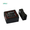
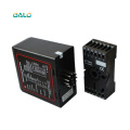
Size of Housing: 78x40x108 mm (L x W x H)
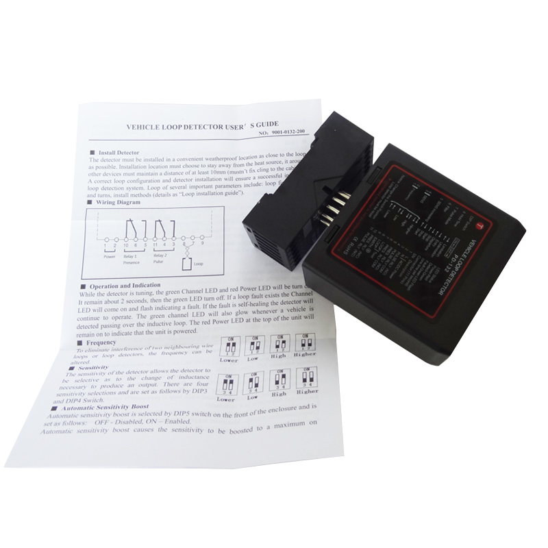
Wiring Diagram
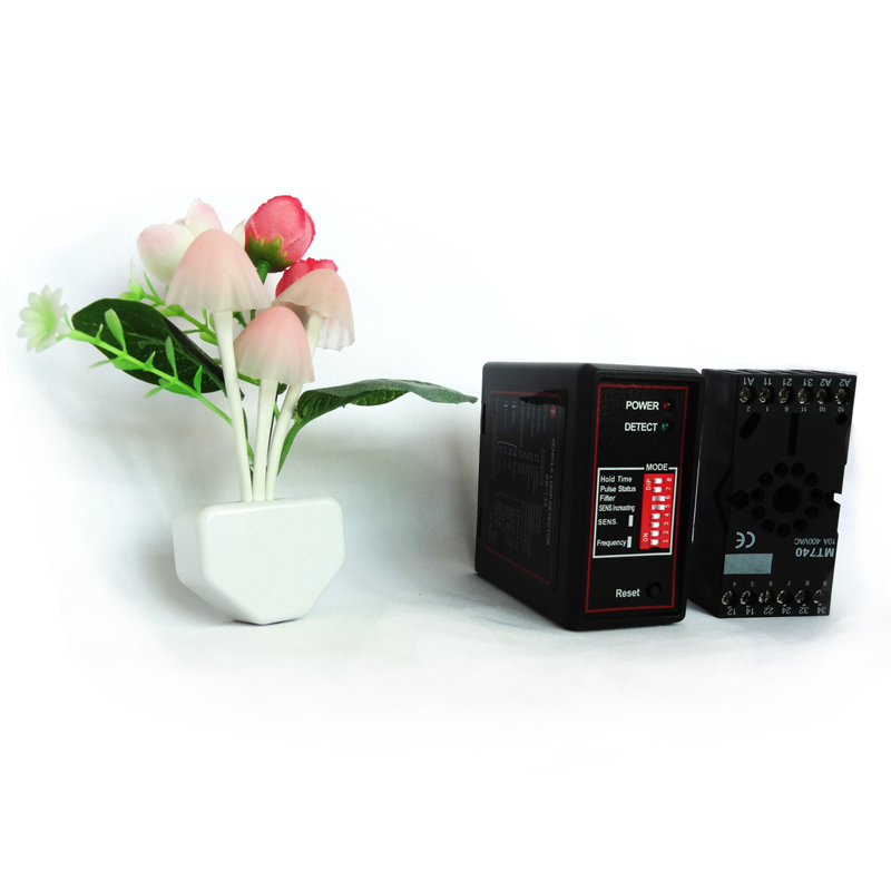
Operation and Indication
While the detector is tuning, the green Channel LED and red Power LED will be turn on. It remain about 2 seconds, then the green LED turn off. If a loop fault exists the Channel LED will come on and flash indicating a fault. If the fault is self-healing the detector will continue to operate.The green channel LED will also glow whenever a vehicle is detected passing over the inductive loop. The red Power LED at the top of the unit will remain on to indicate that the unit is powered.
Frequency
To eliminate interference of two neighbouring wire loops or loop detectors, the frequency can be altered.
Sensitivity
The sensitivity of the detector allows the detector to be selective as to the change of inductance necessary to produce an output. There are four sensitivity selections and are set as follows by DIP3 and DIP4 Switch.
Automatic Sensitivity Boost
Automatic sensitivity boost is selected by DIP5 switch on the front of the enclosure and is set
as follows: OFF - Disabled, ON – Enabled.
Automatic sensitivity boost causes the sensitivity to be boosted to a maximum on detection
on the vehicle, and maintained at this level during the presence of the vehicle over the loop. When
the vehicle departs the loop and detection is lost the sensitivity reverts to the pre-selected level.

Filter
To eliminate interference of the bad environment, the filter mode is activated by setting the DIP6 Switch to “ON” site. In this mode, the reaction time of the detector is delayed, and the sensitivity is reduced. Usually, the filter mode is disabled by setting the DIP6 Switch to “OFF” site.
【Attention】 If the detector isn’t working normally, you must check the loop and wiring at first, and then alter the frequency or the sensitivity. At last, try to set it to filter mode.
Output Relay
If DIP7 is “OFF” site, when a vehicle is detected passing over the inductive loop, the relay1 and relay2 are energized; When the vehicle is detected departing the loop, the relay1 and relay2 are de-energized.If DIP7 is “ON” site, when a vehicle is detected passing over the loop, the relay2 is energized;When the vehicle is detected departing the loop, relay2 is de-energized , and delay 500 ms, the relay1 is energized for 500 ms.
Presence Time
The presence time may be set to permanent presence or to limited presence. In permanent presence mode the detector will continuously compensate for all environmental changes whilst there is a vehicle present over the loop, the presence mode is set with DIP8 Switch and is
configured as follows: OFFLimited Presence ( 10 minutes), ONPermanent Presence
Reset Switch
The detector automatically tunes to the inductive loop connected to it when the power is applied, whether on initial installation or after any break in power supply. Should it be necessary to retune the detector, as may be required after changing any of the switches or after moving the detector from one installation to another, momentary operation of the RESET switch will initiate the automatic tuning cycle.