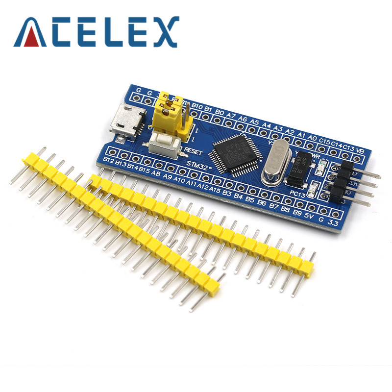
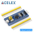
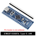
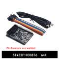
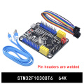
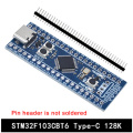
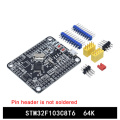
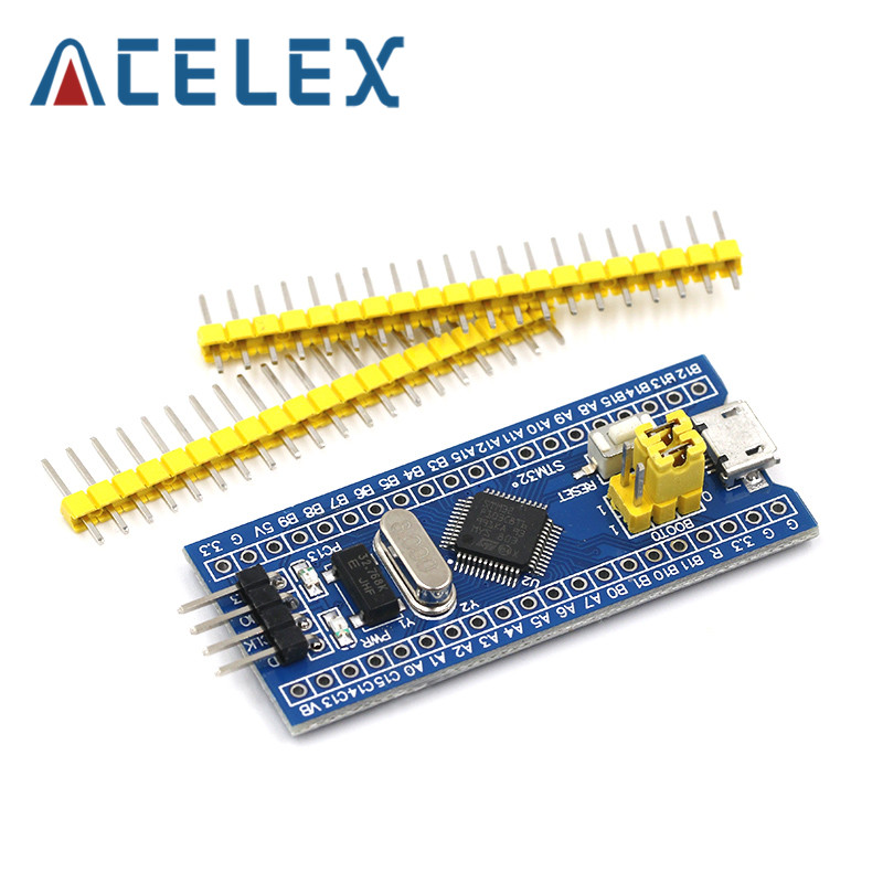
STM32F103C8T6 ARM STM32 Minimum System Development Board Module For arduino
Product Introduction
This is a core chip based on STM32F103C8T6 ARM core board, features are as follows:
1, the board based on the most basic MCU circuit, 8M and 32768 crystal circuit, USB power supply circuit.
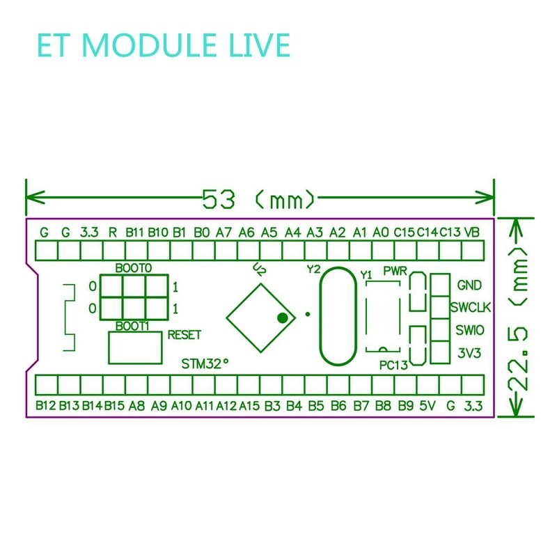
2, the core board is divided into two rows leads to all the I / O port.
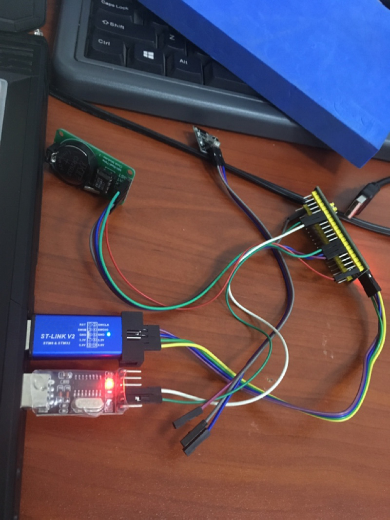
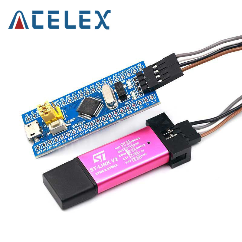
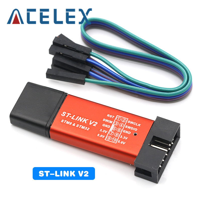
3, with SWD simulation debug download interface, simple and convenient, debugging speed.
4, the use of the Mirco USB interface, you can do USB communication and power supply, USB interface, compatible with the ordinary Andrews mobile phone charger interface.
6, RTC crystal Epson brand, easy to start, more stable.
7, with double pin, but the pin does not default welding, the user according to their own application scenarios to choose their own welding direction. If welding is required, please tell the owner.
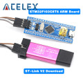
Keil can be used to compile, IAR compiler, can be downloaded through the J-Link or USART1 procedures, the procedures are the owner and debugging procedures, there are problems can consult the owner.
Chip Description:
1, STM32F103C8T6
Package Type: LQFP;
Number of pins: 48;
Kernel: Cortex-M3;
Operating frequency: 72MHz;
Storage resources: 64K Byte Flash, 20KByte SRAM;
Interface Resources: 2x SPI, 3x USART, 2x I2C, 1x CAN, 37x I / O ports,
Analog-to-digital conversion: 2x ADC (12-bit / 16-channel)
Timers: 3 general timers and 1 advanced timer
Debug Download: Support JTAG / SWD debug interface to download, support for IAP.
2, RT9193: 3.3V regulator chip, the maximum output of 300mA.
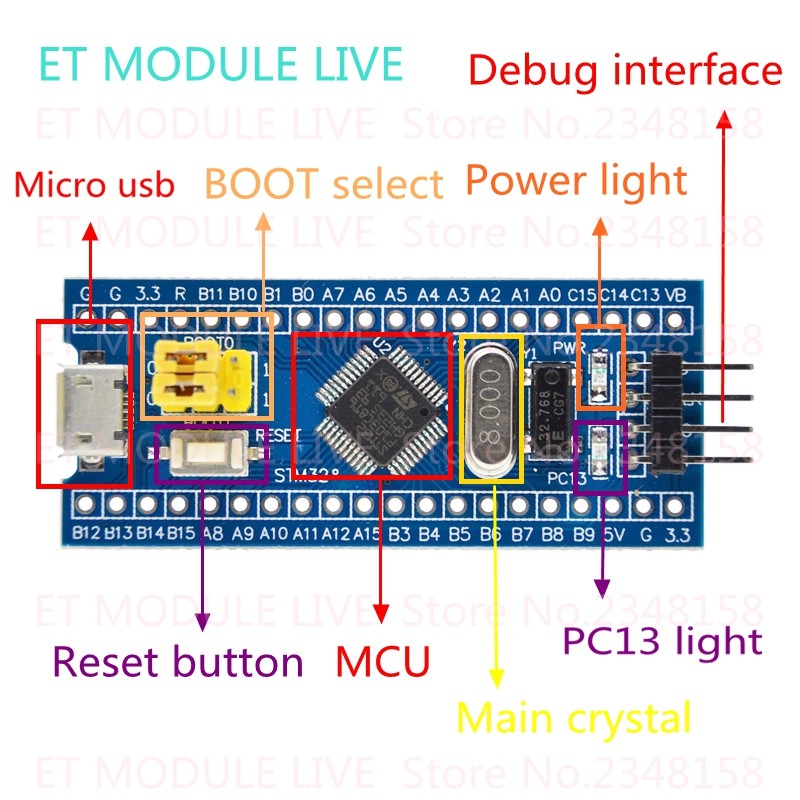
Interface description:
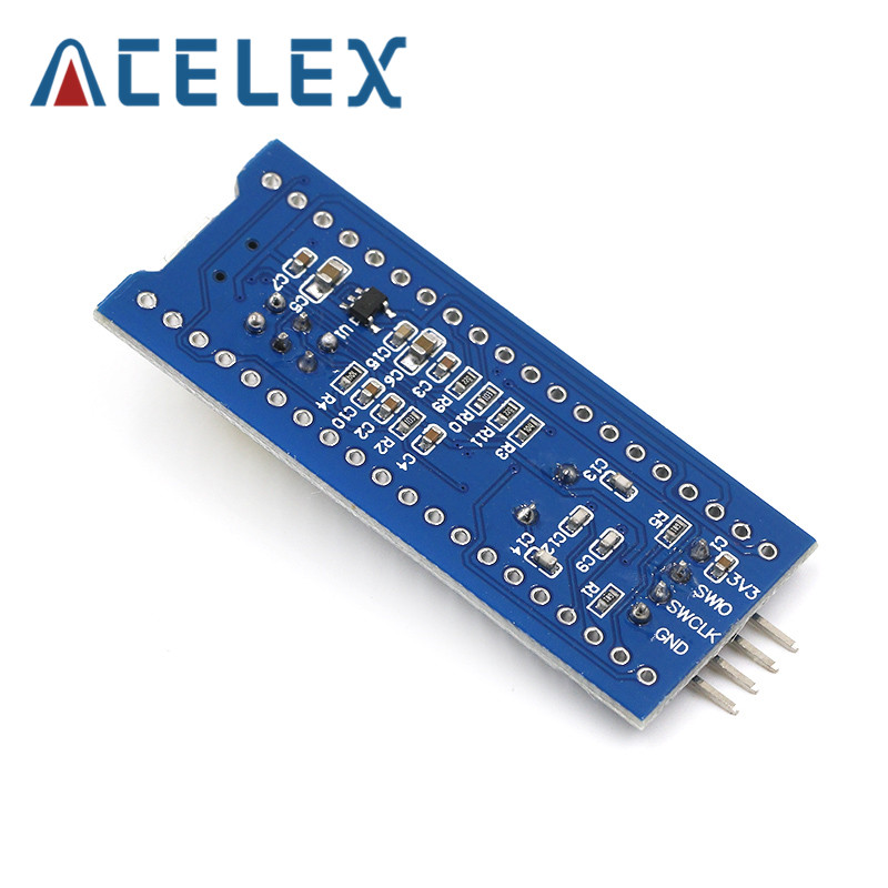
1, SWD interface: support for simulation, download and debug.
2, Mirco USB interface: power supply and USB communication, does not support the download.
3, USART1 interface: USART1 can be used to download the program, or use the USART1 for communication.
4, MCU pin interface: leads all I / O port pins, easy to connect with peripherals.
5, 5V and 3.3V power input and output interface: commonly used in external power supply, or with other modules for common ground treatment
Other Device Description:
1, Power LED (PWR): Power indicator status, can determine whether the power supply is stable.
2, the user LED (PC13): to facilitate the I / O output test or indicate the program running.
3, start jumping choose programming mode: (1, the user flash memory 2, SRAM 3, system memory).
4, reset button: reset chip for the user program.
5, 8M Crystal: The frequency can be set to make the system clocked at 72MHz.
6,32.768KHz Crystal: Available for built-in RTC, or for calibration.
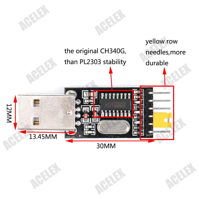
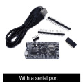
CH340 module USB to TTL CH340G upgrade download a small wire brush plate STC microcontroller board USB to serial
Features:
-
Built-in USB to TTL Transfer chip.
Designed to be used for USB to TTL electronic projects.
TTL interface output, easy to connect to your MCU.
Status LED.
Dual 3.3V and 5V Power output, work with 3.3v and 5v target device.
Size:55mm * 16mm
Server 2008/Win7/Win8 32 bits / 64 bits.
1. support WINDOWS 98/ME/2000/XP/Server 2003/VISTA /
2. 3 V3 and 5V by a short circuit risk selection;
3. not only has the power light PWR, there TXD and RXD indicator, whether the product is easy to learn and intuitive to work in the absence of the instrument in the case;
4. high-quality high-grade yellow pin, pin durable than the black market, beautiful;
5. new original CH340G chips, the chips are recommended STC official USB to TTL chips will not appear due to different driver / different computer as a result of incompatibilities!
CH340 module/ USB switch TTL/ USB transfer RS232/ over PL2303/ STC downloader/ 9 Brush board STC official download chip. Perfectly compatible with all Series MCU STC will not be because of the different drivers that would lead to problems like PL2303 can not download the program. Ultra-stable.